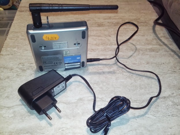
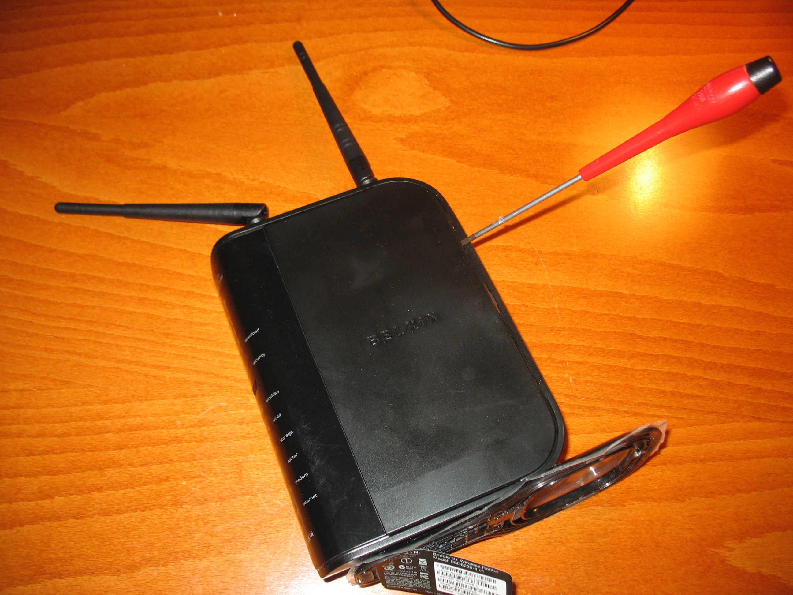
I recently bought a Belkin F6D6230-4 v1, also known as F6D6230uk4, router from eBay UK for £15.99, with free P&P. The router came with its original box, original polyethylene protecting film and looked like new.
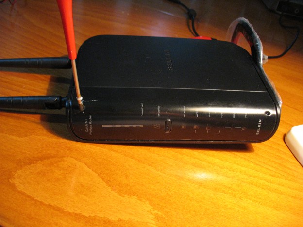
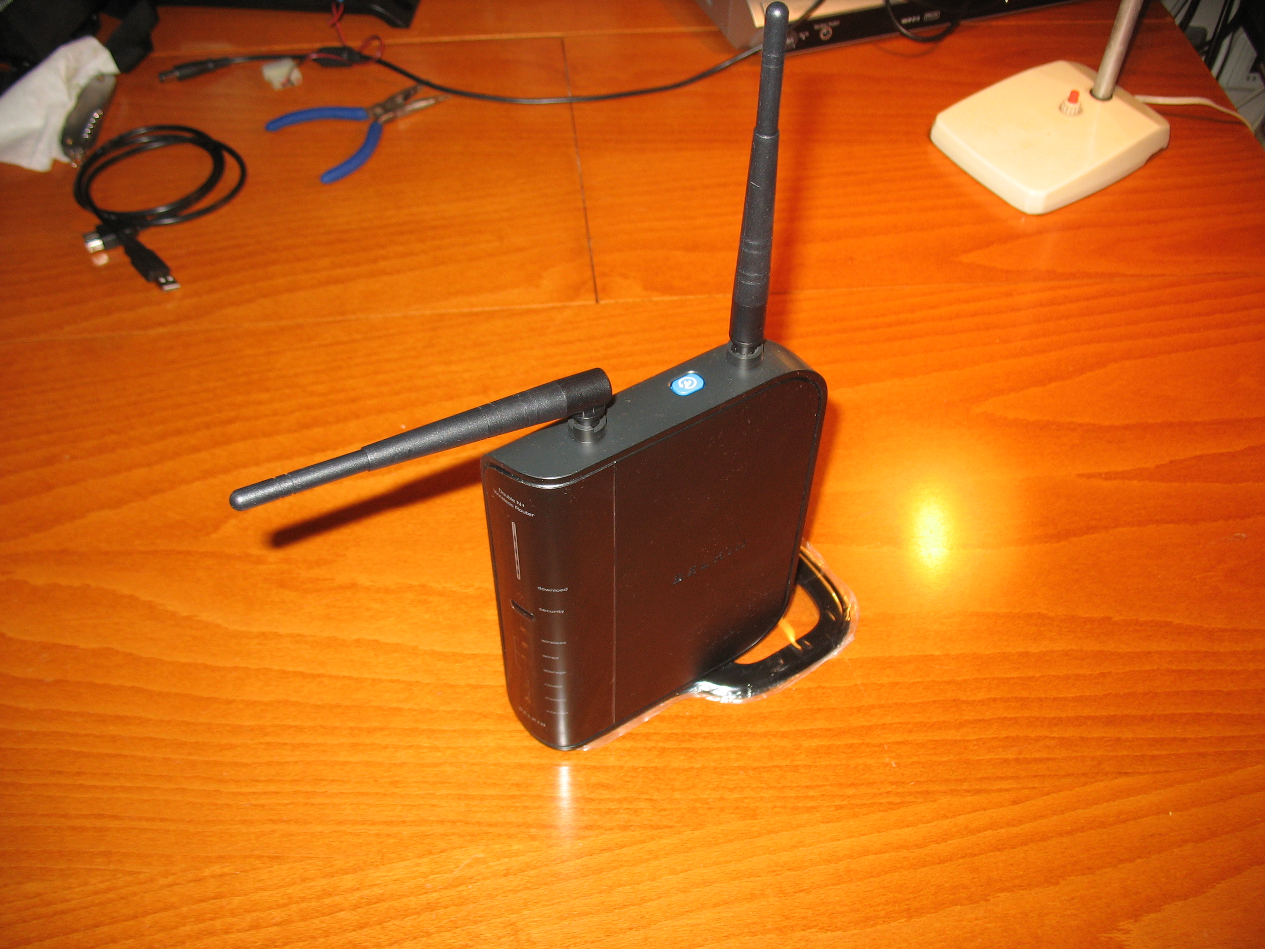 I had read some really negative comments about this model, so I decided to change its firmware with OpenWRT or DDWRT firmware. I spend an evening looking for a successful installation of such firmware, but I didn’t come upon any. The devil, though black and horned, as you can see on the photo, is sometimes not so evil, so I decided to start looking a way to get enough information to port such firmware on it. The first step is to make a research information is available on the internet for that particular model. The second step is to make a tear-down of the hardware in order to see the hardware, and the third step is to make the actual port, or to assist to some person who is responsible for porting the firmware to new router models.
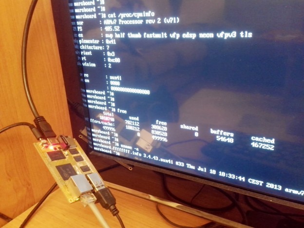
in the first step of the research, I came to the WikiDevi page for this model. this model comes with 8 MB flash memory, 64 MB RAM, BCM4718A1 CPU, in which is integrated the 2.4 GHz radio, and BCM43224 in which is integrated the 5 GHz radio. The router comes also with 1 USB port, 4 LAN ports and 1 WAN port, with a BCM53115 switch chip.
The Teardown
Let’s see the label. The private information is removed.

Label of Belkin F6D6230-4 v1, private information is removed
Now let’s have a look inside. There are two hidden screws under the front panel cover. There are two approaches to unscrew the screws. You can either peel the front panel cover off, or just make holes into it. I preferred the second approach.

F6D6230-4 hidden screws
After that the top cover must be priced:
Pricing of the top cover
Below is given a photo of what we see inside.
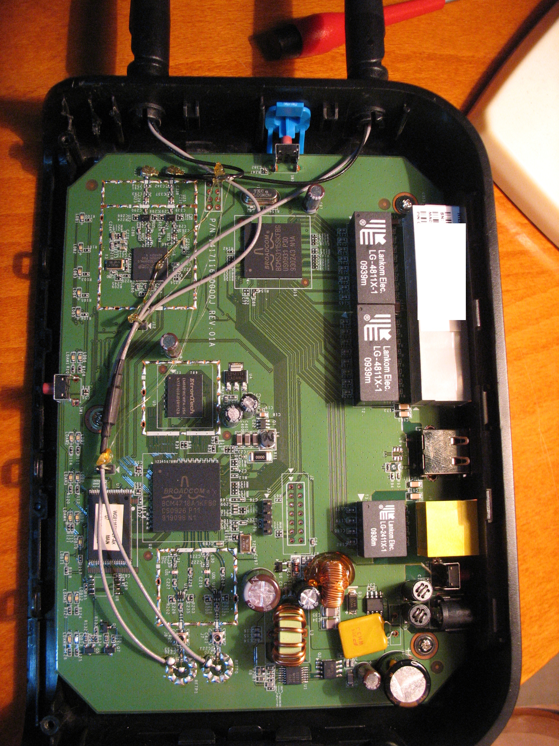
Belkin F6D6230-4 v1 inside
The first things which comes to my attention is that we see that the antennas are used for both 2.5 GHz and 5 GHz bands. Each antenna is fed with 2 coax cables. One of the cables is white and the other cable is black. The white cables seem to be used for 2.4 Ghz, while the black cables are probably used for 5 GHz signals. This brings the question of how efficient the antennas are. Usually combining 2 different bands lowers the efficiency of the antennas. I will leave this question open and will not dismantle the antennas for now.
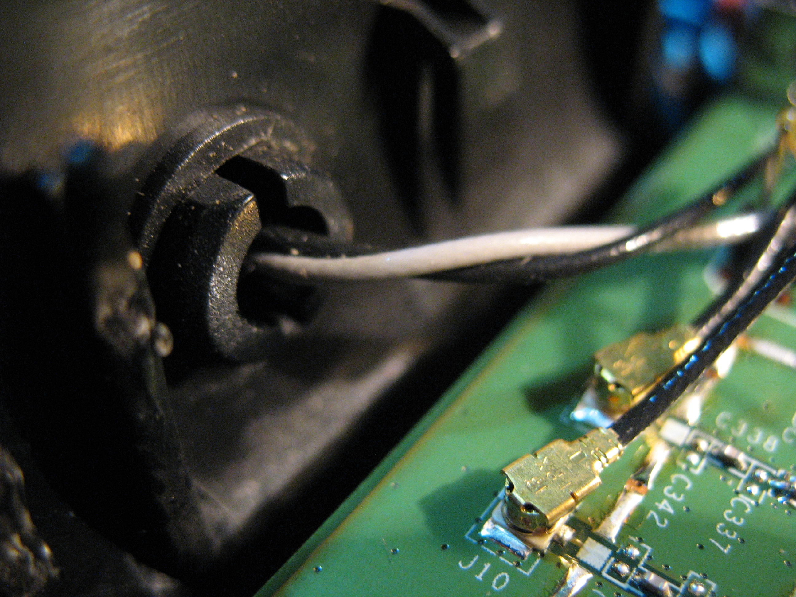
The antenna attachment, You can see both coax cables.
Both antennas are attached permanently. It is not possible to change the antennas without changing the design of the router.
Near the main chip BCM4718A is the serial port connector, and a port for which no pins are soldered, most probably the JTAG connector. You will find how to use the serial connector in the next article of the series for Belkin F6D6230-4.
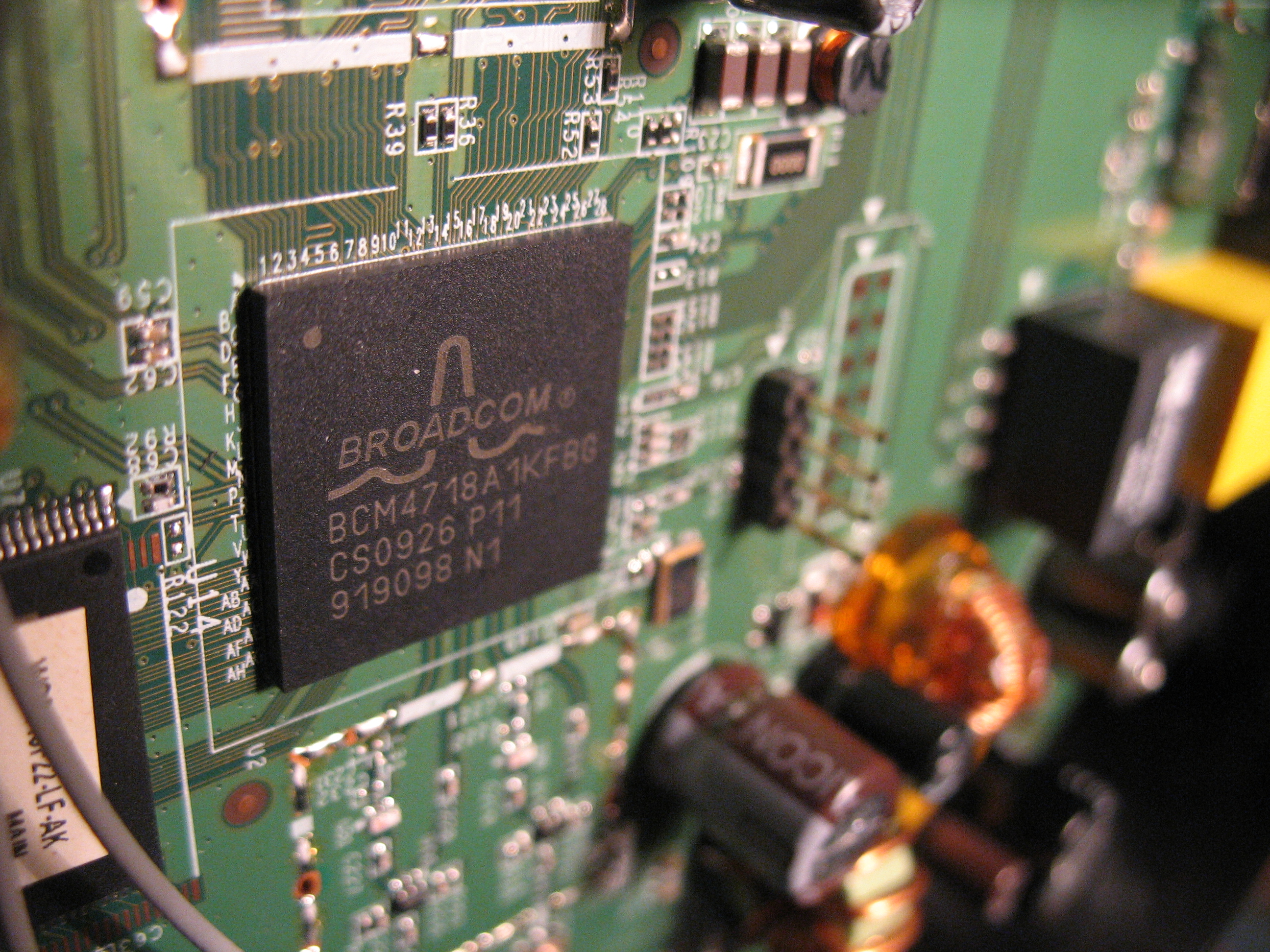
BCM4718A, serial port connector and JTAG
Another view of the chip, the serial connector and the JTAG:
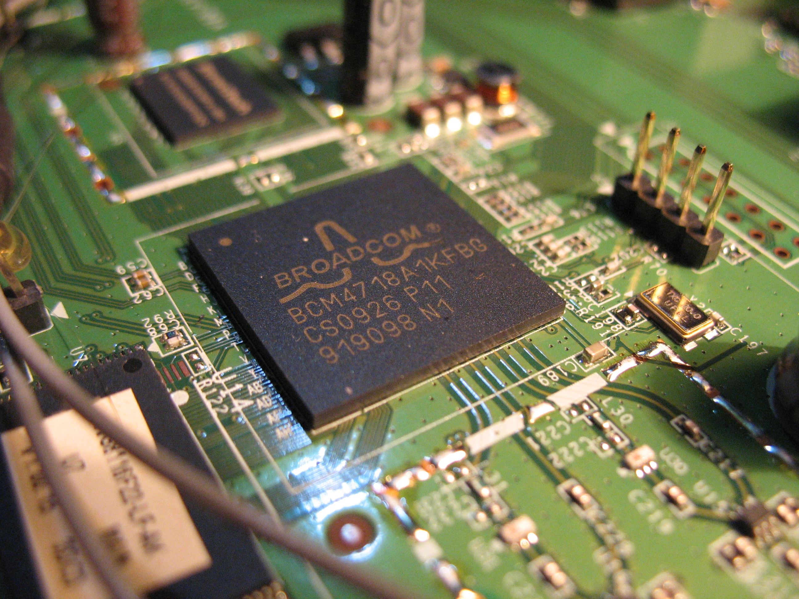
BCM4718A, serial port connector and JTAG – another view
The 5 GHz radio chip is Broadcom BCM43224KMLG. It has a separate quartz oscilator.
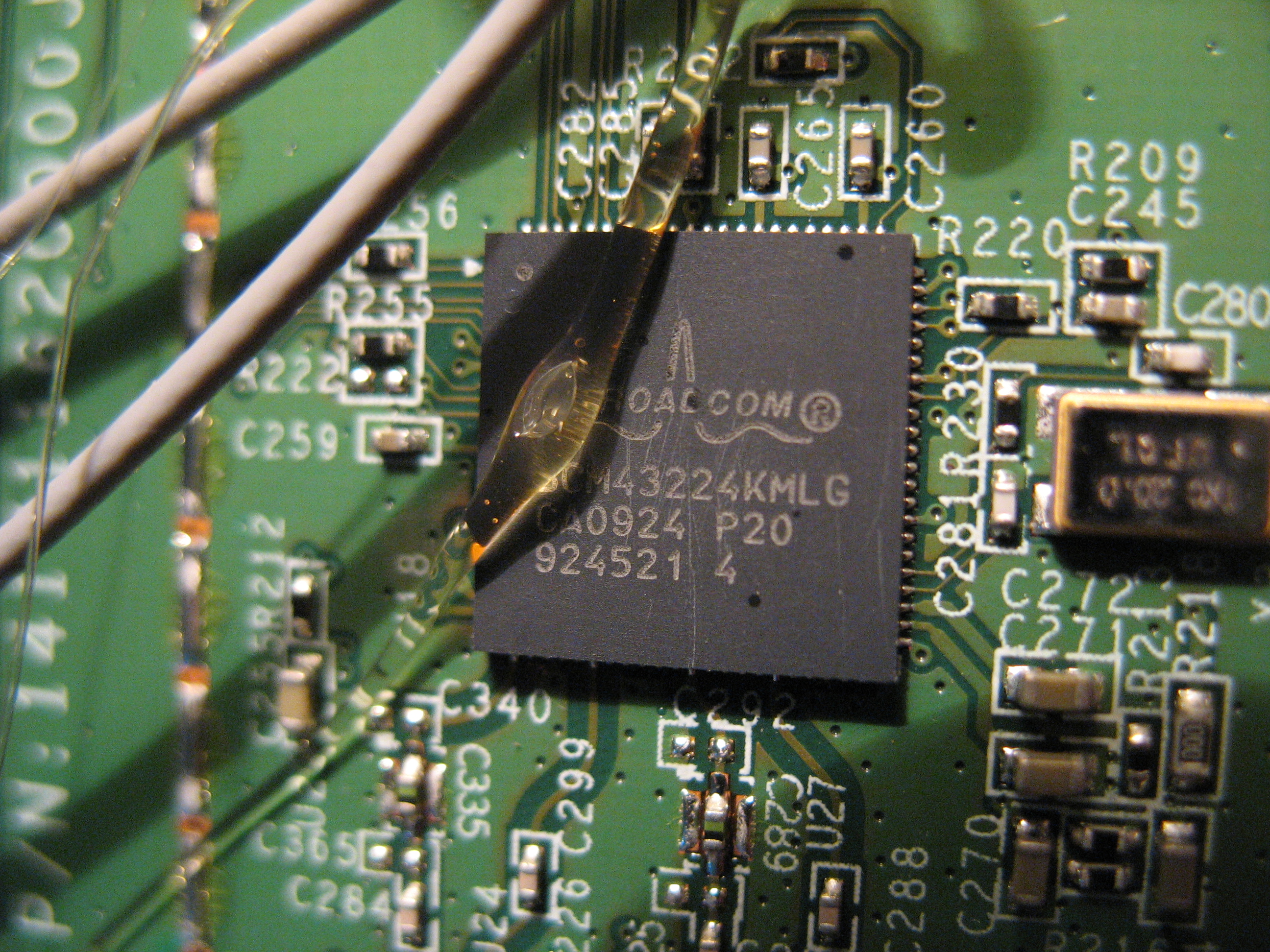
BCM43224
The 5-port ethernet switch chip BCM53115SKFBG is said in its product brief to be for speed 10/100/1000 Mbps. Together with the line transformers LG-4811X-1 it sets the Ethernet speed to 1000 Mbps.

The ethernet switch chip BCM53115SKFBG
The antenna cables are interestingly born by soldered pins.
Antenna cable bearings
The back side of the board is less interesting:

F6D6230 back side of the board

Flash memory of Belkin F6D6230
There are 3 quartz oscillators for the three main chips:


Quartz oscilator for BCM53115

Quartz oscillator for BCM43224
The RAM memory is EnronTech EM68B16CWPA-25H, 32 M x 16 bit, DDR2, 400 MHz.

EM68B16CWPA-25H
Interesting notice
I noticed something very interesting while playing with the router. The main chip BCM4718A gets very hot. When I put my finger on the chip, I almost feel pain, which means the temperature is over 60 degrees Celsius, about 140 degrees Fahrenheit, which is the temperature threshold for feeling pain. Many of the complaints for this router are related to the system stability, and it is very likely the poor stability is related with the overheating of the central processor, which works in synergy with the poor firmware.
Conclusion
The system parameters of this router look quite good, its price is just right for its current firmware suport, but for the future the device seems a bit underestimated. I hope that with a heatsink for the BCM4718A chip and an open source firmware, this router will become a pearl in the crown in my home network.