The intelligent WiFi mains socket is a device which is inserted into the original mains plug and has a mains socket itself. The mains output of the device can be controlled and switched on/off over an Internet connection.
The Itead Sonoff smart socket caught me with its simple design and with the possibility to upload custom firmware. The 10 amps socket is controlled by the WiFi capable ESP8266 microcontroller. ESP8266 is the leading platform for budget IoT devices. Its SDK is free and is well documented. It has built in WiFi, TCP/IP stack, free compiler and tools.
The device is produced by ITEAD studio, based in Shenzhen, China, website https://ww.itead.cc. The wiki product page is https://www.itead.cc/wiki/S20_Smart_Socket. In the Downloads section of this page https://www.itead.cc/wiki/S20_Smart_Socket#Downloads you can find the product schematics.
The socket comes in EU, US, UK, and China versions. This review covers the EU version of the socket, however most of the statements should be valid for the other versions.
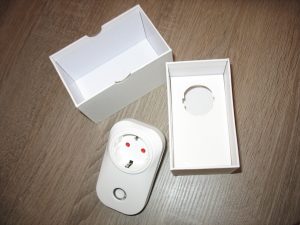
The device comes packed into a solid cardboard box. The box is custom for the version of the smart socket and clearly shows how the specific plug looks like.

The box in which the socket is sold
The box looks quite luxurious from inside. There is a cardboard piece which supports the plug and is probably also customized for the version of the socket as on this piece there is a profile of an EU plug.
The socket unboxed
The external look shows a well built plastic case. The touch of the socket feels quite solid like an expensive device. The holes of the socket are fitted with child protection. There is a single button on the front of the socket.
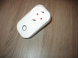
Front of the socket
On the back of the socket there is an adjunct plug. On the plug there are explicit marks for L (line), N (null) and ⏚ (ground). A warranty seal with red Chinese inscription covers a hole with a screw which allows dismantling of the socket. A label reads:
WiFi Smart Power socket
Model: S20_EU
Input: AC 110 – 240V
Max Power: 2000W
Power Consuming: ≤ 0.3W
If we are not catchy for the funny English, the label is quite informative. As there is quite a wide voltage range, it seems the same schematics are used for all versions of the socket, and probably S20_EU is the EU version of the socket, S20_US is the US version of the socket, S20_UK is the UK version of the socket and S20_CN is the China version of the socket. The mains frequency 50 Hz or 60 Hz is not stated, as it is probably not important for the pulse switching power supply.
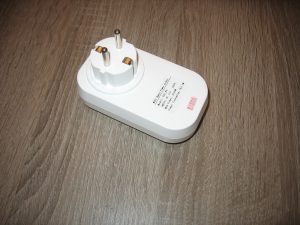
Back of the socket
Now let’s look what is inside. We remove the warranty seal and undo the screw. Once you have undone the screw, there are several plastic locking fingers which have to pried
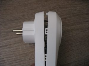
The socket pried from the side
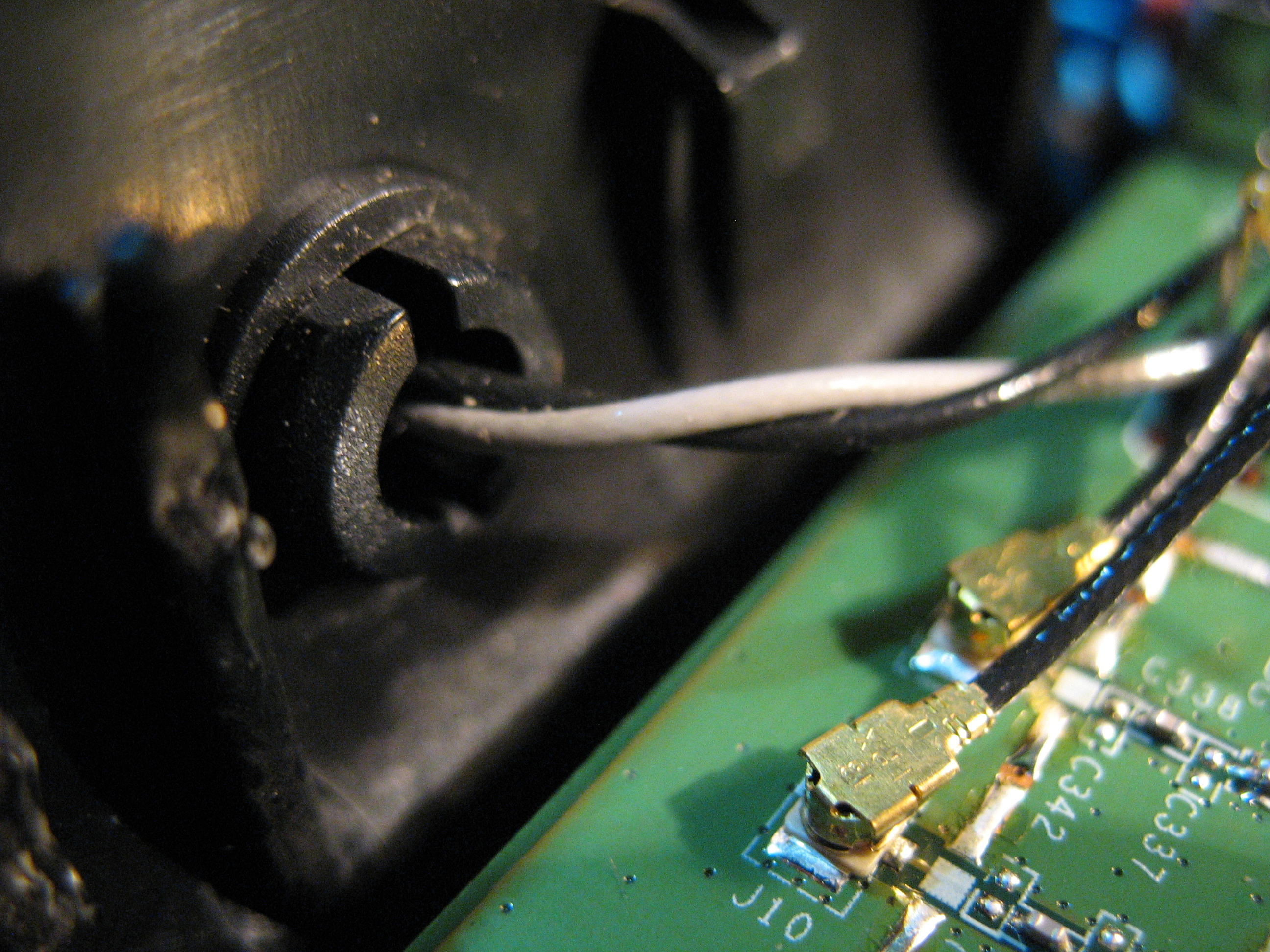
The firs look inside shows the wires are welded to the plug with electrical current. The pros for such welding are the high temperature and corrosion stability of the welding. The cons are that if the control of the welding is not good, weak electrical connection may occur.
The wiring looks quite neat. There is no foreseeable chance of a wire to melt down its isolation and to short circuit another wire, or a conducting surface to mechanically touch another conductive surface with the opposite potential. There are springs which create pressure for good electrical contact between the socket and the plugs which will be inserted. The discrete electronic components are well spaced from one another.
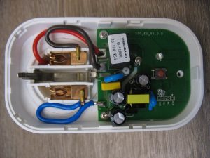
The front of the socket opened
There is an inscription on the board which reads S20_EU_V1.0.0 . After all it seems that they use different boards for the EU, US, UK and China variants.
On the electrical relay there is a label which reads:
PSA B01 GL
100001a720
p/w: WWJG000627
The first line looks like a software version. The second line looks like a MQTT ID of the unit, and the third line is either a part number, or a password which allows access to the unit or with which the unit accesses a server.
The electronic board can be easily separated from the enclosure after undoing the two screws which support the board. The third screw which supports the board is the screw which is used to open the case of the socket and it has already been undone.
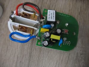
The socket board extracted
The power cables are soldered to the board. This is a point where weaknesses can appear, but with good control of the soldering this is OK. The cables conveniently keep the shape they had while in the enclosure, thus making the assembly to be easy.
if we look at the back of the board, we see insulation channels cut in the board which keep the low voltage part of the board from the high voltage part. The power lines on the board are tinned in order to carry more current.
The back of the extracted socket board
On the bottom we can see the ESP8266 chip with a label
ESP8266EX
482015
P48A17
The WiFi antenna can be seen in the bottom left of the picture.
In the bottom right can be seen an 8 Mbit, i.e.1MB, serial flash with label
winbond
25080BVSIG
1451L
.
This means the socket has plenty of space for firmware.
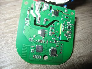
Let’s return to the front of the board.
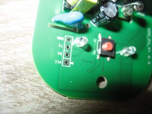
The serial port of the board
To the right of the button there is a RGB LED, which is used to indicate the status of the smart socket. To the left of the button there are 4 lines VCC, RX, TX and GND which can be used for programming. The button itself is connects GPIO0 of ESP8266EX to the ground, so when the board is powered while the button is pressed, ESP8266 enters programming mode and new firmware can be flashed.
In the upper right corner we can see a 10 A fuse which is meant to protect the high-power circuit in case of current overload.
Finally let’s look at the power relay.
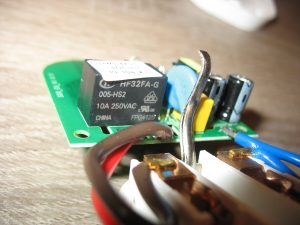
The relay of the socket
The relay has a label
HF32FA-G
005-HS2
10A 250VAC
CHINA FP0412B
The 10A of the relay give a little safety factor of 10% over the advertised switching power of 2000 W for 220 V mains voltage. To stay on the safe side, I would use the power socket for loads of up to 1000 W.
I purchased the socket from Aliexpress https://www.aliexpress.com/item/Itead-Sonoff-Wif-Wireless-Remote-Control-Switch-Smart-Home-10A-16A-Universal-intelligent-DIY-Timer-Switch/32760053192.html , for $16.70, with shipping via Singapore Post for $1.73. The item was dispatched and delivered very quickly.
If you want to gain experience with ESP8266 there is a free SDK, documentation, cheap hardware modules and plenty of programming examples freely available in Github and other sites.